In this tutorial we start where we left off after setting up a complete Proxmox home lab with an old home computer and a home switch.
Read the First Article!
This article is base on our earlier guide on How to Set Up a Home Lab using Proxmox!
Read it first!
Our goal is to create proper VLANs for each subnets we have configured in our home lab, so DHCP will work perfectly.
At the moment if we connect a new virtual machine or a physical computer in our lab system, they will get an IP address automatically in our default home subnet. We want to be able to connect the new device to a VLAN where we have custom subnets and DHCP services configured.
So if one of our subnet is 10.0.1.0/24, we either connect it to it's dedicated VLAN in Proxmox, or if it's a physical device we connect it to a port on our home switch where that particular VLAN is set. This way they get an IP address in that 10.0.1.0/24 subnet.
We can do this with as many subnets we want. Again, the idea is to dedicate a separate VLAN for each individual subnet, giving them their own broadcast domain. This is how networking is properly done in a professional environment 🙂 .
What We Need for VLANs
We assume the Proxmox home lab is fully configured as shown in our earlier article.
There, we did not care if the small home switch was managed or unmanaged. In this case however we will need a managed switch so we can configure VLANs on it.
In this particular case we had a Netgear GS105Ev2 managed switch lying around.
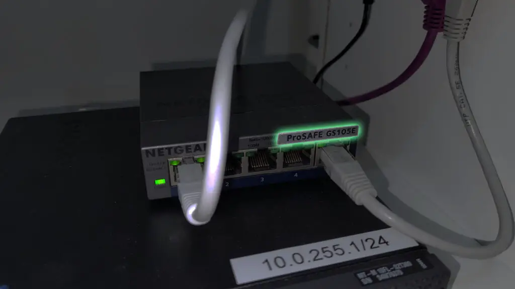
This guide shows the configuration steps of this particular model, however if you have a different make/model the idea behind the configuration steps is the same, only the interface might be different.
Set Up the Home Switch
Most managed home switches have a WebUI interface through which they can be configured. The details of that user interface is usually printed on the bottom of the switch, like so:
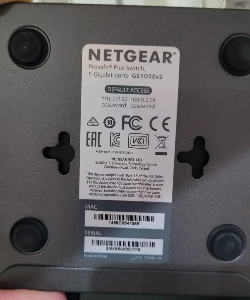
It says the switch has a default IP address of 192.168.0.239/24. Unfortunately our home subnet is different, it's 10.0.255.0.24
This means we first need to change the IP address of the switch to manage it from our home network.
1. Grab a network cable and connect you computer or laptop to any unused ports on the switch.
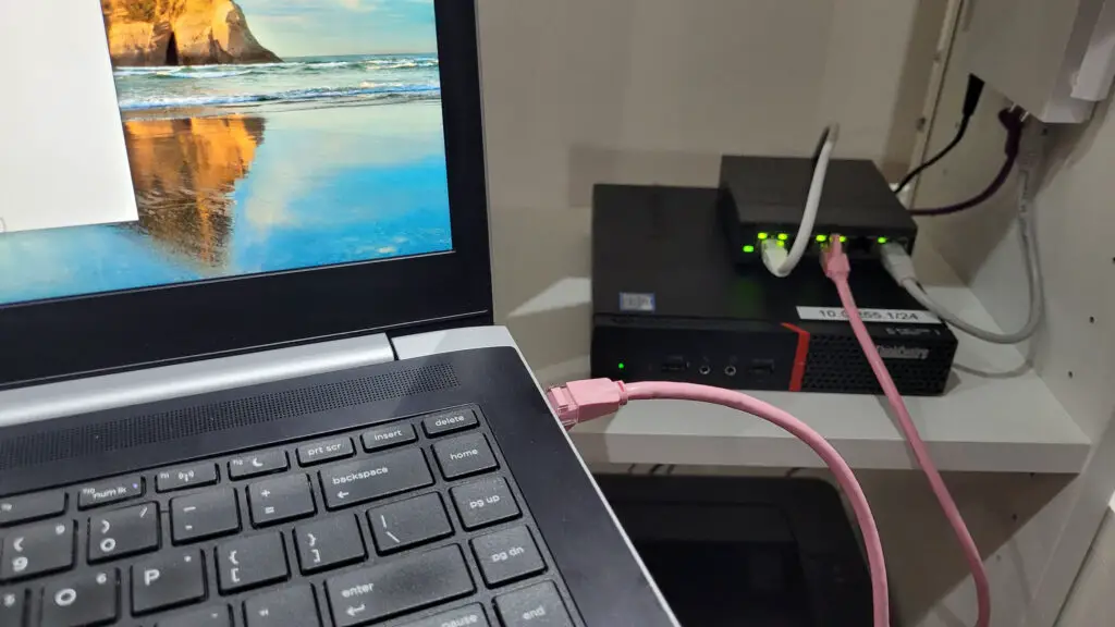
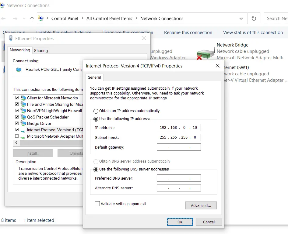
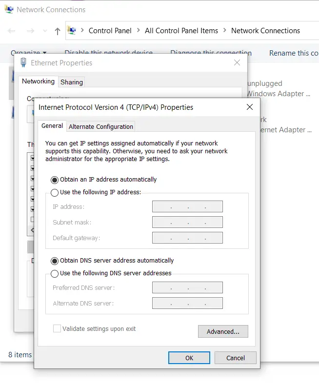
2. On the computer open up the Network and Sharing Center (Win key + R, then ncpa.cpl, and hit Enter). Right-click on your Ethernet LAN interface, choose Properties and under the Internet Protocol Version 4 option configure an IP address in the switch's subnet.
We go with 192.168.0.10/24. Default gateway and DNS servers are not necessary in this step so we leave those blank.
3. Next, we open up a web browser on the computer and navigate to http://192.168.0.239/ to access the WebUI.
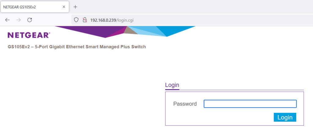
4. Log in using the default password of password, then on the landing page disable DHCP mode and set a free IP address in your home subnet. We use 10.0.255.251/24, our home router (gateway) address is 10.0.255.254 (again, your network is likely different, check the network configuration on your computer by opening a command prompt and using the ipconfig command).
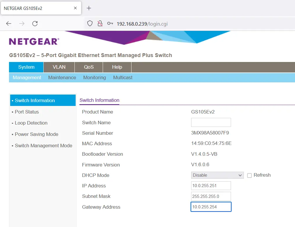
After we save the configuration we can reset the interface on our laptop to obtain IP addresses automatically, disconnect the network cable because we don't need it. We are ready now to set up the VLANs on the switch.
Set Up VLANs on the Switch
1. Open up the WebUI on any computer in your home network. The admin portal on the switch is now accessible from any machine on your LAN.
In our example the portal is here: http://10.0.255.251/
2. On the top menu click on VLAN, then just below it select the 802.1Q option. To the left click on the Advanced sub-menu and highlight the VLAN Configuration button.

Enable it.
3. Here we see that the default VLAN1 is set on all ports as the untagged VLAN. What we want is to add two new VLANs to the mix, one for each of our internal subnets: VLAN101 and VLAN102.
Under the VLAN Configuration tab, in the VLAN ID field type in 101, then hit Add on the top.
Repeat this with VLAN 102.
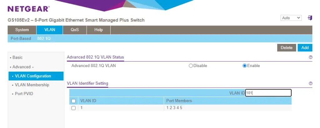
Good, now we have VLAN1, VLAN101 and VLAN102 available on the switch.

Configure VLANs on Switch Ports
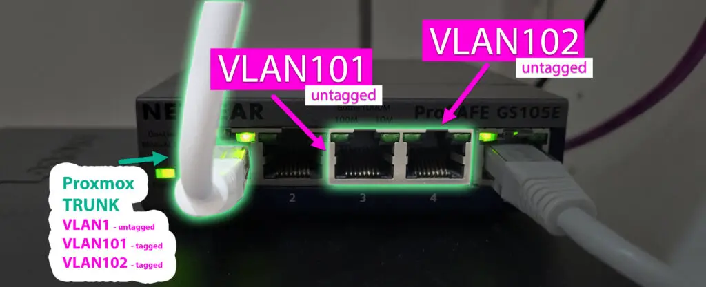
Now this is the important part: we want to dedicate one port on the switch for VLAN101 and another one for VLAN102 so when a device is plugged into them, they will access the proper subnet automatically.
Also we'll configure the port connecting to our Proxmox computer to carry those two VLANs.
To achieve this, we need to set untagged traffic on VLAN101 on port 3, and VLAN102 on port 4 for the client.
We also need to configure port 1 (the Proxmox computer connection) to have VLAN101 and VLAN102 available for tagged traffic.
Tagged, untagged VLAN
Before we continue a word about the concept of tagged and untagged VLAN.
What is a LAN?
A local area network is a network segment where broadcast messages are traveling unrestricted. For instance when a new device is connected to the network, it will need an IP address to communicate with the others.
To get one, it starts to be shouting out: "Hey, I need an IP address, can I get one?" on the universal FF:FF:FF:FF:FF:FF broadcast MAC address. All the connected nodes will hear this message and the DHCP server on the network will respond back, giving the new computer and IP.
What is a VLAN?
Smart people recognized that bigger networks might need multiple LANs, or in other words broadcast domains (a domain where when a devices shouting all other nodes hear it). For instance in our example, we have our home network, plus we set up two other subnets for our lab.
This means we'd need three different switches to set this up properly.
With VLANs (virtual local area networks) we can have over 4000 virtual LANs configured on the same device. In our case that means we can set up our three subnets on three virtual LANs using only one single network switch device!
What is Tagged and Untagged?
When we use a network switch we are probably not even aware that we use VLANs already, VLAN1 to be precise.
When a packet is sent through a switch port, it's automatically put on VLAN1. The fact that the information packets don't contain any information on what VLAN they should be using means this traffic is untagged. That's how the switch works by default.
However, we can add a tag to each packets we send saying we want that packet to be using a specific VLAN. That case the packet is tagged and if that particular VLAN is allowed on the switch port, it will use that virtual LAN.
So in a nutshell a switch port can have one untagged VLAN configured, where untagged traffic will be put automatically. Note, that this VLAN can be the default VLAN1 or it can be anything else!
Furthermore we can over 4000 more tagged VLANs on the same port.
Effectively imagine that: port1 on the switch is configured to have VLAN1 untagged, and VLAN101 and VLAN102 tagged. If we send regular (untagged) traffic through the port we'll access all the other devices on VLAN1 that are present in our network. If we send a packet with VLAN101 tagged, that packet can be heard by all devices accessing VLAN101, but devices on VLAN1 will not hear it.
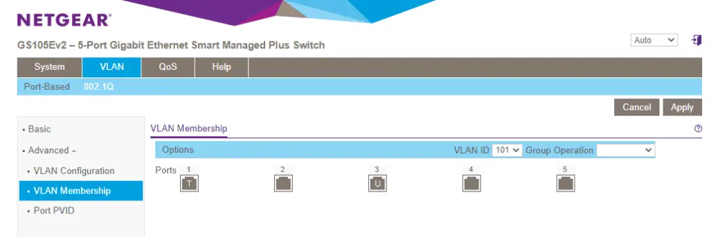
1. Set up VLAN101 untagged on port 3. Click on VLAN membership on the left side, then select VLAN101 from the dropdown menu on the top. Click on port 3 so the letter U appear in the middle.
While you are there click twice on port 1. The T will symbolize tagged traffic being allowed on the port.
Save the config by clicking on Apply.
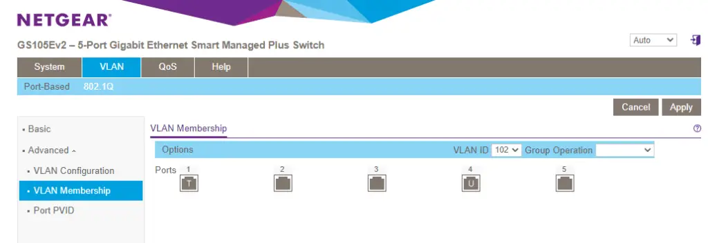
2. Repeat this with VLAN 102 on port 4.
3. The the PVID on port 3 and 4. This means the default VLAN that the port accesses with untagged traffic.
Select on Port PVID in the left side menu.
First check the box in front of port 3, then put 101 in the PVID text area. Hit Apply.
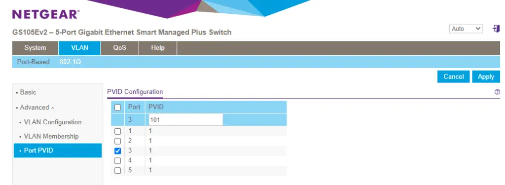
Now check the box in front of port 4, and put PVID 102 in the text field. Apply the changes.
You should see the new config showing like so:
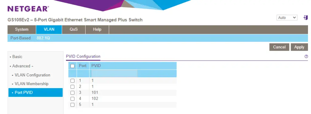
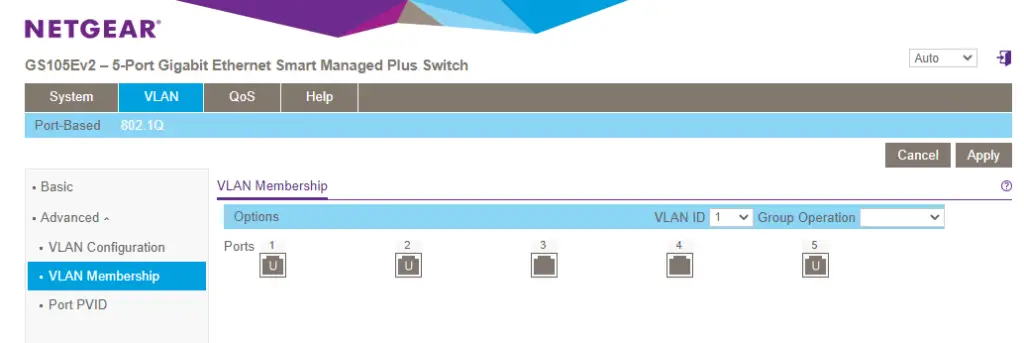
The last thing we need to do on the switch is to remove the untagged flag for VLAN1 on port 3 and 4. They have VLAN101 and VLAN102 untagged, doesn't need the original VLAN1 anymore.
Click on the VLAN Membership button on the left again. Click twice on both port 3 and 4 so the tag in the middle disappears. Save the config by hitting Apply.
Configure VLANs on Proxmox
Our physical setup is all configured for VLAN traffic. We still need to make our Proxmox host VLAN aware.
1. Open up the Proxmox WebUI. Navigate to http://[Proxmox IP or hostname]:8006/
I have added my Proxmox node to my hosts file so I simply use http://pve:8006/
Here's my C:\windows\system32\drivers\etc\hosts file for reference:
# Copyright (c) 1993-2009 Microsoft Corp.
#
# This is a sample HOSTS file used by Microsoft TCP/IP for Windows.
#
# This file contains the mappings of IP addresses to host names. Each
# entry should be kept on an individual line. The IP address should
# be placed in the first column followed by the corresponding host name.
# The IP address and the host name should be separated by at least one
# space.
#
# Additionally, comments (such as these) may be inserted on individual
# lines or following the machine name denoted by a '#' symbol.
#
# For example:
#
#      102.54.94.97     rhino.acme.com          # source server
#       38.25.63.10     x.acme.com              # x client host

# localhost name resolution is handled within DNS itself.
#	127.0.0.1       localhost
#	::1             localhost

10.0.255.1	pve
2. In the portal right-click on the hostname of your Proxmox box, and select Shell.
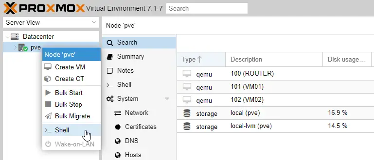
3. IMPORTANT: install the Open vSwitch package on the Proxmox system by running these two commands.
apt update
apt install openvswitch-switch
4. In the terminal open the /etc/network/interfaces file for editing.
vi /etc/network/interfaces

# Or if you are not familiar with vim, use nano:
nano /etc/network/interfaces
Our original file looks like this:
auto lo
iface lo inet loopback

iface eno1 inet manual

auto vmbr0
iface vmbr0 inet static
        address 10.0.255.1/24
        gateway 10.0.255.254
        bridge-ports eno1
        bridge-stp off
        bridge-fd 0
This is the new config we go with, configuring a VLAN aware OVS switch as vmbr0.
# The loopback network interface
auto lo
iface lo inet loopback

# The virtual network switch
auto vmbr0
iface vmbr0 inet manual
  ovs_type OVSBridge
  ovs_ports eno1 vlan1 vlan101 vlan102

# The primary network interface
auto eno1
iface eno1 inet manual
  ovs_bridge vmbr0
  ovs_type OVSPort

# Configure the management interface on vlan1
auto vlan1
iface vlan1 inet static
  ovs_type OVSIntPort
  ovs_bridge vmbr0
  address  10.0.255.1/24
  gateway  10.0.255.254
  ovs_mtu 1500
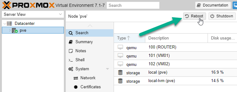
Save the config and reboot Proxmox.
Connect our pfSense ROUTER to the right VLANs
Before configuring the router itself we need to make sure the virtual interfaces of the router are connecting to the right VLANs.
1. Click on our ROUTER virtual machine (see earlier article), and highlight the Hardware tab.
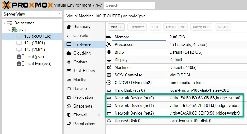
2. Network Device (net0) is the external interface of the ROUTER so untagged traffic flows in VLAN1 which is good. No changes needed her.
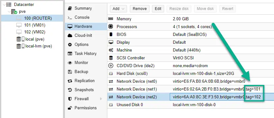
Network Device (net1) is the subnet1 interface so we add it to VLAN101. Double-click on it, and put 101 in the VLAN Tag box. Hit OK.

Network Device (net2): the second internal interface connect to VLAN102.
This is what you should see after setting up the virtual network devices on the VM:
Configure our pfSense ROUTER
Now start up the ROUTER VM. It should already work fine, we just check if the DHCP service runs fine on both Subnet1 (10.0.1.0/24) and Subnet2 (10.0.2.0/24).
1. Open your pfSense management portal (see earlier article).
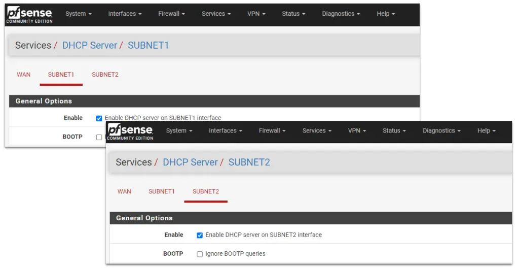
2. Navigate to Services/DHCP Server, and make sure the DHCP service is enabled on both SUBNET1 and SUBNET2. If they are not running, enable them.
Test Connectivity
We've done configuring the system, hooray!!!
It's time to test it.
1. First, connect VM01 to VLAN101 and VM02 to VLAN102 respectively. Click on them, on the Hardware tab double-click on the Network Device option, and put in the required VLAN ID (101 or 102).

2. Start up the VMs. Their interfaces are already configured with static IP addresses, so we ping VM02 (10.0.2.10) from VM01 to test network connection.
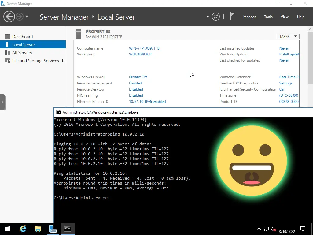
Beautiful!
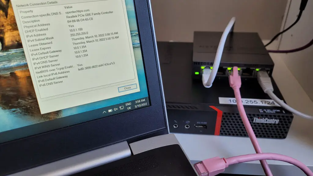
3. Last test it connecting a physical laptop to port 3 and see if it gets IP addresses automatically from Subnet1.
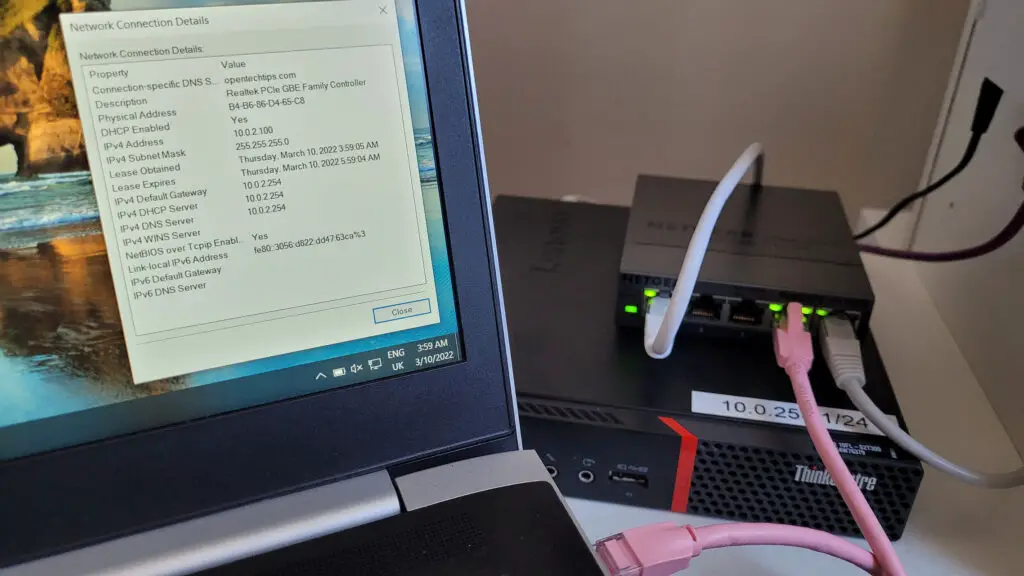
And after connecting to port 4, the laptop instantly gets an IP address of 10.0.2.100/24 from the DHCP service! 🙂
I'd like to continue this series and set up a physical pfSense router next if there is a demand. Please let me know if you are interested in the comment section!
Thank you 🙂

Interested in the router article!
Good Morning, Zsolt Agoston
Great article, I am real impressed with your knowledge of both Netgear switchs,VLans and Promox. I would love to see you do more articles around these 3 subjects. Thanks for your hard work, Awesome article! Thank you very much,
Michael
Thanks for this great work.
I wonder how to configure everything when I want VLAN 101 and VLAN102 on the same managed switch port. (I have a single NIC laptop with OPNSense on it and I defined multiple VLANs (via Other Type) under the LAN interface.)
Additional info:
ISP router connected to port 5 of the managed switch
OPNSense laptop (1 NIC) connected to port 4 of the managed switch.
LAN network (cabled) connected to port 3 of the managed switch.
My Proxmox server (1 NIC pc) is on the LAN network.
I want to be able to have the VLANs defined on the OPNSense laptop available in Proxmox.
Could you descibe this as well in a tutorial?
Thanks!