In this exercise I set up 10 extra VLANs on the LAN interface of my virtual pfSense instance. The setup is running on a Proxmox hypervisor.
Our design objective is to have separate subnets configured on these new VLANs, also DHCP service provided by the pfSense router.
This way when a new client connects to the VLAN it will automatically receive an IP address granting intra- and inter-subnet connectivity, also access to the Internet.
I also show you how to set up a home switch to access any of these new VLANs.
My home lab setup
If you are interested in the home lab I'm working on check my guide on how it is built from scratch!
Prerequisites
- Proxmox computer (pre-installed and configured) - see guide above
- pfSense instance for routing and DHCP service - also check the guide linked above
I. Add the new VLANs to the Proxmox virtual switch
First we need to make sure that the virtual switch built into Proxmox has the new VLANs added. This ensures that traffic is enabled on them.
Basic VLAN setup on Proxmox
If you are interested in a more detailed tutorial on setting up VLANs on Proxmox check out my guide HERE.
1. Install Open vSwitch
If Open vSwitch is not installed on your Proxmox server (it is not by default!) make sure you install it before jumping to the next step!
a. Open a shell window on the Proxmox server. In the management portal right-click on the hostname of your server (for example pve), and select Shell in the dropdown menu.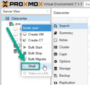
b. Install the openvswitch-switch package on Proxmox
apt update
apt install openvswitch-switch
2. Set up the virtual switch for Proxmox
In the same terminal window edit the /etc/network/interfaces file.
Attention: Interface name and IP address!
I attach my original and also the modified config file below. Yours will be very similar, however pay attention to the physical interface name (in the example it's eno1, yours is likely different)! Also make sure you use your IP address that your Proxmox box currently has, otherwise you'll lose connectivity to the hypervisor.
Open the config file with vi or nano:
vi /etc/network/interfaces

# If you are not familiar with vim, use the nano editor:
nano /etc/network/interfaces
Original /etc/network/interface:
auto lo
iface lo inet loopback

iface eno1 inet manual

auto vmbr0
iface vmbr0 inet static
        address 10.0.255.1/24
        address 10.0.1.1/24
        address 10.0.2.1/24
        gateway 10.0.255.254
        bridge-ports eno1
        bridge-stp off
        bridge-fd 0
Now update the configuration, following the new interfaces file as a template. Remember to use your physical interface name (ex. eno1) and your previous IP address on the interface(s). Proxmox knows that you want to utilize the new built-in virtual switch and adds the existing (default) VLAN1 and also the additional VLANs (from VLAN11 all the way to VLAN20) to the mix!
New, updated /etc/network/interface:
# The loopback network interface
auto lo
iface lo inet loopback

# The virtual network switch
auto vmbr0
iface vmbr0 inet manual
  ovs_type OVSBridge
  ovs_ports eno1 vlan1 vlan11 vlan12 vlan13 vlan14 vlan15 vlan16 vlan17 vlan18 vlan19 vlan20

# The primary network interface
auto eno1
iface eno1 inet manual
  ovs_bridge vmbr0
  ovs_type OVSPort

# Configure the management interface on vlan1
auto vlan1
iface vlan1 inet static
  ovs_type OVSIntPort
  ovs_bridge vmbr0
  address  10.0.255.1/24
  gateway  10.0.255.254
  ovs_mtu 1500
II. On Proxmox: configure the LAN interface of pfSense
We need to make sure that the LAN interface of the pfSense box is set up as a trunk port, this gives access pfSense to all required VLANs .
Browse to the ROUTER virtual machine (our pfSense installation) on Proxmox,. On the Hardware tab double-click on the second NIC (Network Device), which is the LAN interface on our router.
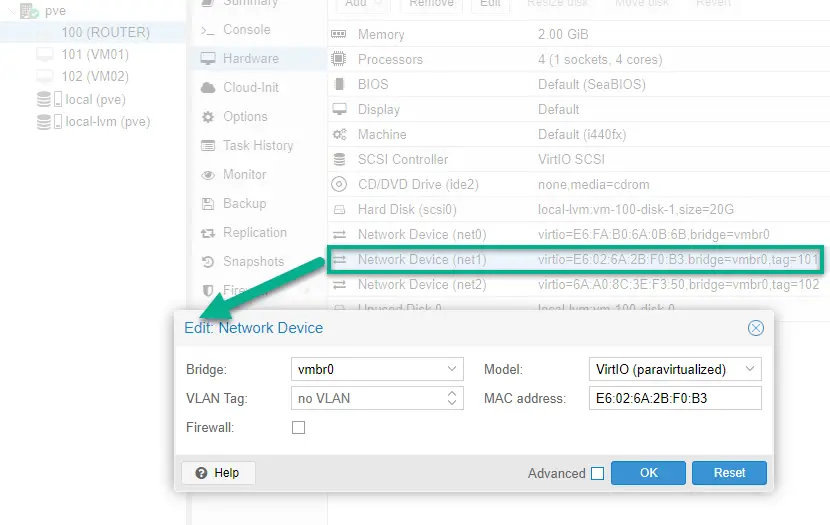
Make sure that no VLAN tag is set. This ensures the interface will access all VLANs, technically acting as a trunk port.
I also remove the third NIC (net2) because we'll only need two interfaces on pfSense from now on: an external (WAN) interface and a LAN interface for all of our new VLANs and subnets.
III. Reconfigure the pfSense router interfaces, adding VLANs
Now we are ready to start up pfSense.
It will recognize the configuration change, so we set up its interfaces from scratch in our terminal window. You might also want to set up a brand new pfSense installation from scratch in this occasion. That case go ahead and after first boot this initial setup will greet you on a fresh pfSense instance.
1. Open a terminal to pfSense by double-clicking on the virtual machine name in the Proxmox portal.
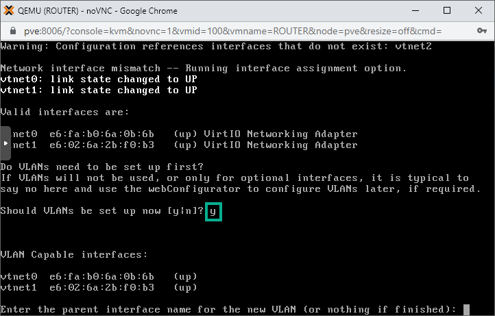
2. When asked type in y for VLAN setup. This way we'll be able to create separate virtual interfaces for all the VLANs. As a result we'll end up with one physical interface (vtnet0) set up as the WAN (external) interface, and ten LAN interfaces accessing ten separate VLANs.
3. Our LAN facing interface is called vtnet1 (as seen in the illustration), so we type in vtnet1 as the parent interface when asked. We also add the VLAN number. First is VLAN11 so we type in 11.
Then repeat the whole process for each ten VLANs.
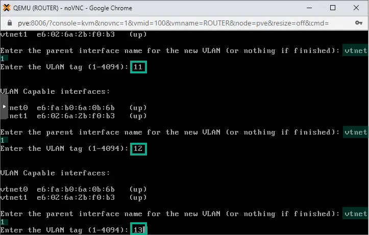
After the sub-interface for VLAN20 is created, simply hit Enter to finish.
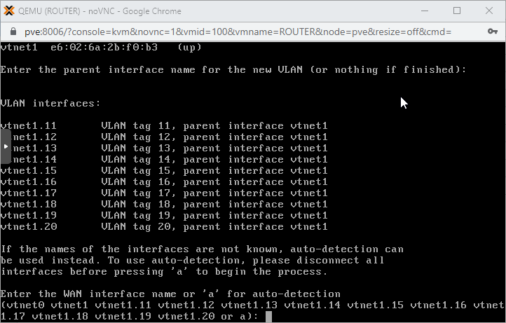
Sub-interfaces are created as seen above, each is easy to identify. For example the sub-interface accessing VLAN11 is called vtnet1.11, the VLAN12 interface is marked as vtnet1.12, etc
At a later step we'll be assigning proper IP addresses to each of these just like we do with normal physical interfaces.
4. Time to assign our interfaces. When asked type in vtnet0 as the WAN interface. Then add the rest interfaces as LAN ports.
Note that for LAN interfaces omit vtnet1, we don't need that. Use the sub-interface names instead, strating with vtnet1.11 and go on until reaching vtnet1.20!
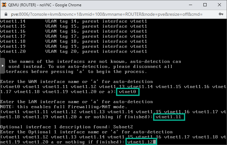
Go on until vtnet1.20. Then next leave the field empty and hit simply Enter to finish adding interfaces to the list.
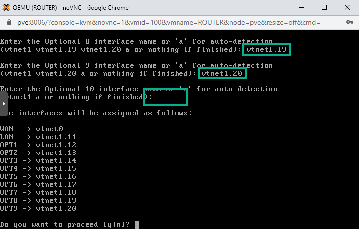
Type in y to proceed!
IV. Set up IP addresses on the pfSense interfaces
We can add IP addresses to the new interfaces in the console or we can do it on the pfSense WebUI.
We already have set up the external interface through which we could access the WebUI, however it's simpler just doing it in the command line so we proceed in the black and white terminal 🙂
The best part is that we'll be able to configure the DHCP service for each new subnets so after this step we're done with the setup and can go testing !
1. In the main menu enter 2 for IP assignment and hit Enter.
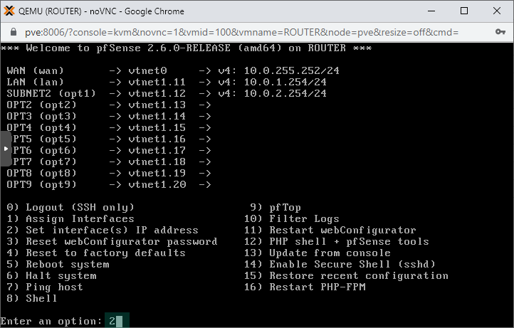
2. We use the 192.168.X.0/24 subnet for each VLAN X. So on interface2 that is accessing VLAN11 we'll set up 192.168.11.254/24 as the IP address.
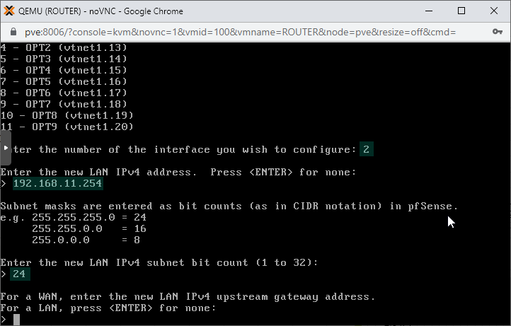
We also configure the DHCP service on the subnet, using the IP range of 192.168.11.100 - 192.168.11.249 for the DHCP clients. This is the address pool from where IP addresses will be picked for new clients connecting to the subnet.
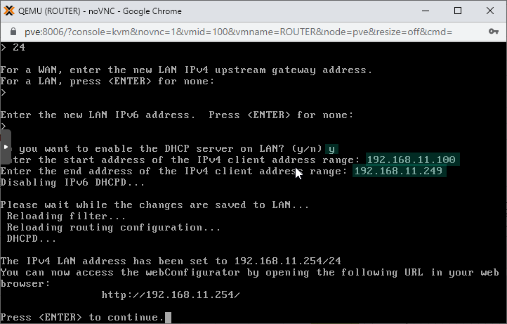
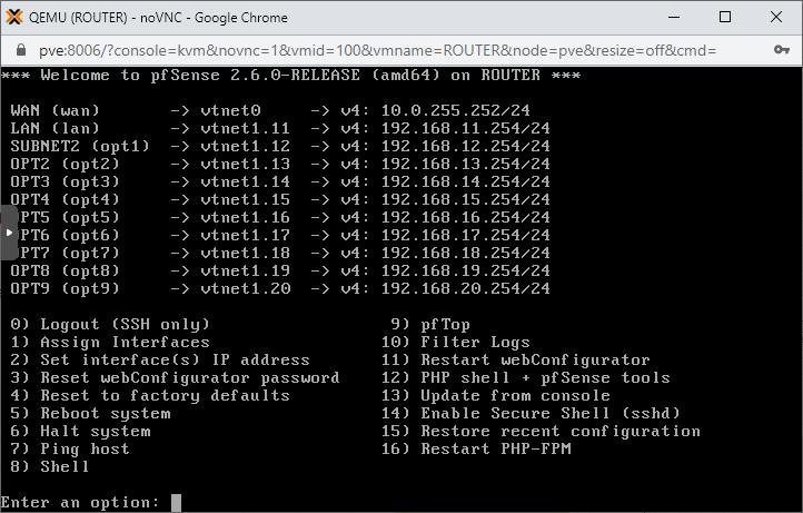
3. Repeat the whole process with the remaining LAN interfaces: interface3 - interface11
After the last interface is set, this is how the IP assignment configuration should look like:
V. Configure the Firewall to Allow Traffic
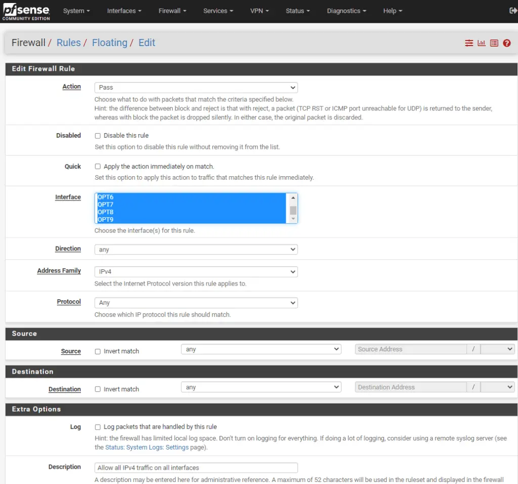
On the pfSense WebUI, under the Firewall/Rules/Floating tab make sure you have a rule that allows IPv4 traffic on all interfaces. Click in the Interface box, and use CTRL + A to select all.
VI. Configure the Physical switch with VLANs
If you want to access the new VLANs from physical devices please follow this guide to set up a Netgear switch to access specific VLANs.
If this example we have a 8-port Netgear GS308E managed switch, and we set port1 to access VLAN11, port2 to access VLAN12 and port3 has VLAN13 as the untagged VLAN on the interface.
VII. Testing Our VLAN Setup - Only Virtual
1. Set the NIC (Network Device) of the virtual machines of pfSense
For clients to access the right VLAN we need to tag it on their virtual interface.
a. Select a VM on pfSense, we pick VM01 from our earlier example. Double-click on the Network Device option in its Hardware tab and type 11 in the VLAN Tag field. This means VM01 will access VLAN11.
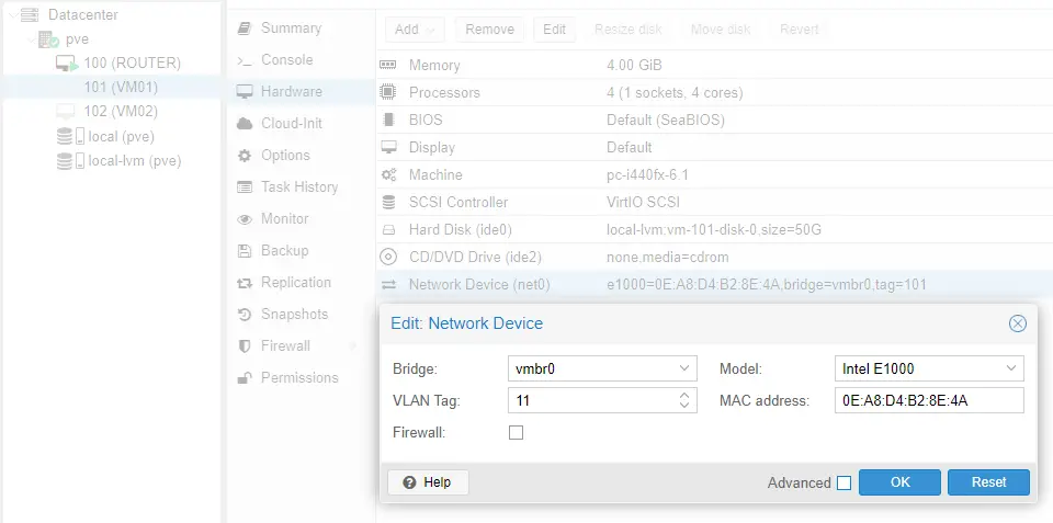
b. Repeat this step with VM02, only there select VLAN12 for tagging.

2. Start VM01 and VM02 virtual machines up.
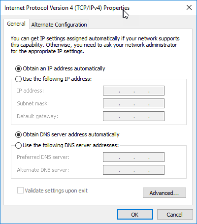
3. Make sure both of their Ethernet interfaces have automatic IP and DNS setup selected (ncpa.cpl, then select the interface, Properties/IPv4/Properties).
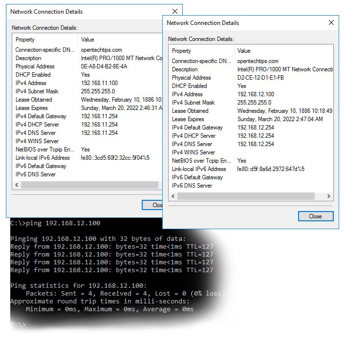
As seen below they have 192.168.11.100 and 192.168.12.100 set respectively and they can communicate!
VIII. Testing Our VLAN Setup - Physical
Lastly, I use our laptop to test the physical switch if they work fine with the setup.
First I plug it in port1, where I should get an IP address in the 192.168.11.0/24 subnet.
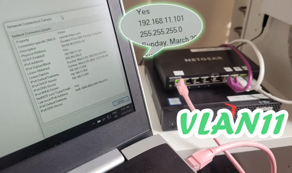
Plugging it in port2 on the switch the laptop automatically obtains an IP in subnet12!
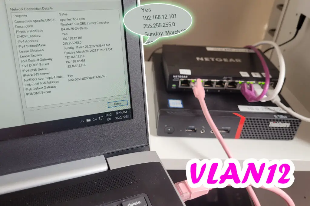
And port3 clearly accesses VLAN13, getting an IP in subnet13!
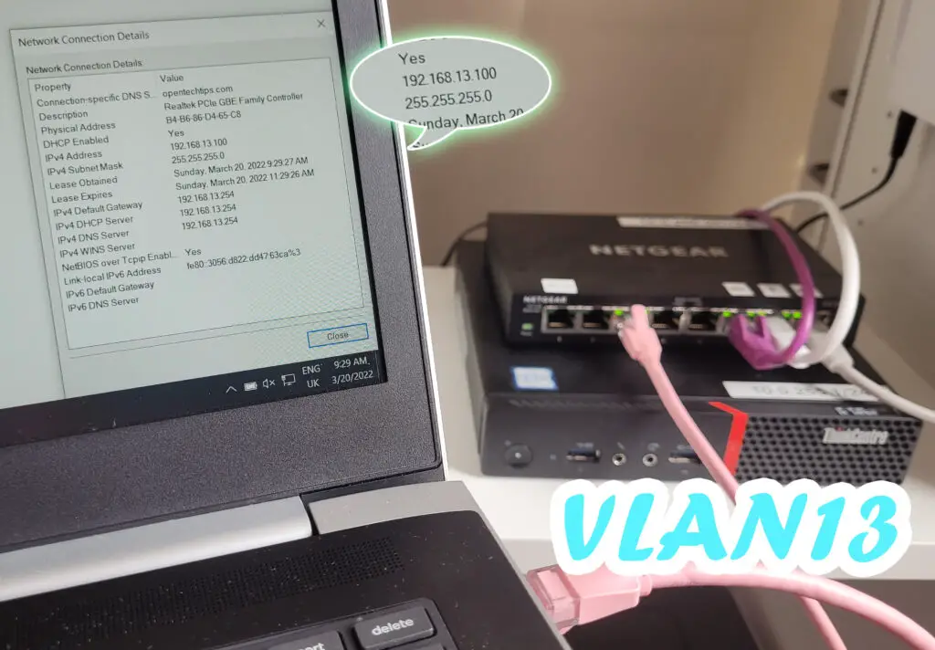
All done! If you followed along, enjoy your network setup at home!

hi, thanks for this exercise.
And with two network cards in my proxmox server?
i have a network card for wan and another for lan.
Modem is connected to my wan port and lan port is connected to my switch.